
TM 5-2420-231-23-3
0233
LEFT-HAND TUBES REMOVAL CONTINUED
NOTE
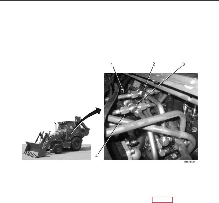
Note routing of loader lift cylinder hydraulic tubes to aid in installation.
9. Disconnect tube (Figure 12, Item 1) from fitting (Figure 12, Item 2)
10. Disconnect tube (Figure 12, Item 4) from fitting (Figure 12, Item 3).
11. With assistance, remove two tubes (Figure 12, Items 1 and 4) from machine.
Figure 12. Tubes (Left-Hand).
0233
END OF TASK
CLEANING AND INSPECTION
0233
Clean and inspect all parts IAW Mechanical General Maintenance Instructions (WP 0369).
END OF TASK