
TM 5-2420-231-23-3
0235
REMOVAL CONTINUED
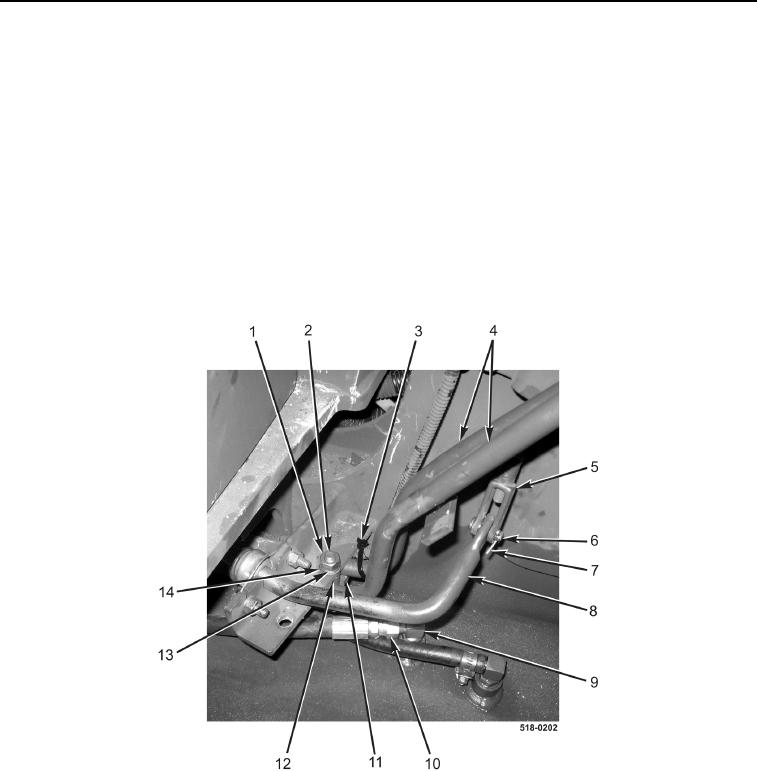
16. Remove nut (Figure 5, Item 1), lockwasher (Figure 5, Item 14), flatwasher (Figure 5, Item 13), bolt (Figure 5,
Item 2), bracket (Figure 5, Item 11), and spacer (Figure 5, Item 12) from two tubes (Figure 5, Item 4). Discard
lockwasher.
17. Remove cotter pin (Figure 5, Item 7) from clevis pin (Figure 5, Item 6). Discard cotter pin.
18. Remove clevis pin (Figure 5, Item 6) and clevis (Figure 5, Item 5) from loader self-leveler control lever
(Figure 5, Item 8).
NOTE
Note location and quantity of tiedown straps to aid in installation.
19. Remove tiedown strap (Figure 5, Item 3) from tube (Figure 5, Item 4). Discard tiedown strap.
20. Disconnect hose (Figure 5, Item 10) from fitting (Figure 5, Item 9). Position hose aside.
Figure 5. External Cab Connections.
0235