
TM 5-2420-231-23-3
0238
REMOVAL CONTINUED
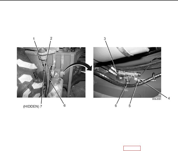
6. Remove nut (Figure 3, Item 4), lockwasher (Figure 3, Item 5), bolt (Figure 3, Item 1), washer (Figure 3, Item 2)
and spacer (Figure 3, Item 7) from hydraulic valve (Figure 3, Item 3). Discard lockwasher.
7. Disconnect two hydraulic hoses (Figure 3, Item 6) from hydraulic valve (Figure 3, Item 3).
8. Remove hydraulic hoses (Figure 3, Item 6) from machine.
Figure 3. Hydraulic Valve.
0238
9. Repeat steps 1 through 8 for right side.
END OF TASK
CLEANING AND INSPECTION
0238
Clean and inspect all parts IAW Mechanical General Maintenance Instructions (WP 0369).
END OF TASK