
TM 5-2420-231-23-3
0239
DISASSEMBLY
0239
NOTE
The procedure for stabilizer load check valve disassembly and assembly is identical for
left-hand and right-hand stabilizer load check valves. Right-hand stabilizer load check
valve is shown in this procedure.
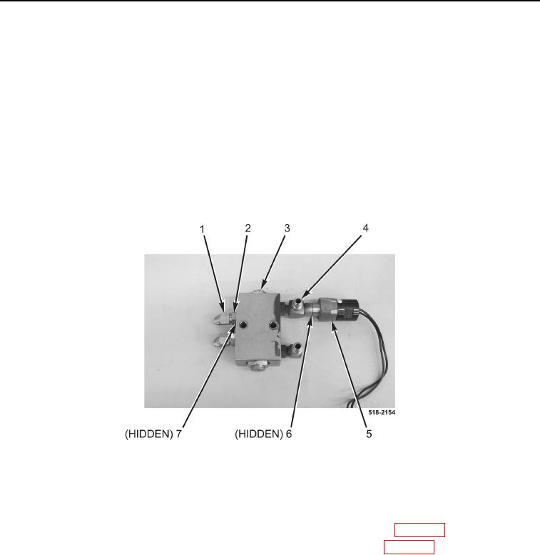
Note location and orientation of fittings to aid in assembly.
1. Remove pressure switch (Figure 4, Item 5) and O-ring (Figure 4, Item 6) from fitting (Figure 4, Item 4). Discard
O-ring.
2. Loosen four nuts (Figure 4, Item 2), remove fittings (Figure 4, Item 1) and O-rings (Figure 4, Item 7) from load
check valve (Figure 4, Item 3). Discard O-rings.
3. Repeat steps 1 and 2 on left-hand load check valve.
Figure 4. Fittings.
0239
END OF TASK
CLEANING AND INSPECTION
0239
1. Clean and inspect all parts IAW Mechanical General Maintenance Instructions (WP 0369).
2. Clean and inspect all parts IAW Electrical General Maintenance Instructions (WP 0370).
END OF TASK