
TM 5-2420-231-23-3
0239
INSTALLATION
0239
NOTE
Remove plugs and caps from hoses and fittings.
Install lines as tagged and marked during removal.
The procedure for stabilizer load check valve removal and replacement is identical for left-
hand and right-hand stabilizer load check valves. Right-hand stabilizer load check valve is
shown in this procedure.
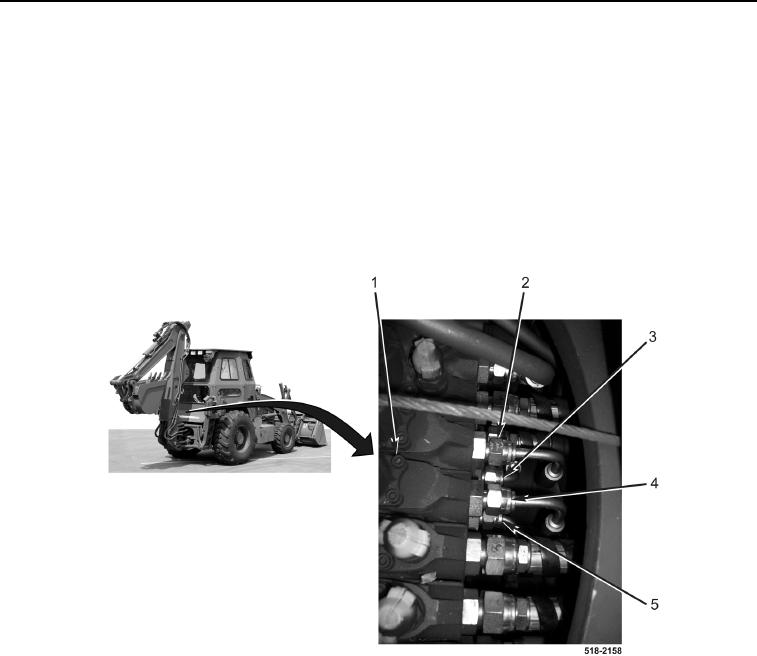
1. Install left-side hoses (Figure 6, Items 4 and 5) on loader valve (Figure 6, Item 1).
2. Install right-side hoses (Figure 6, Items 2 and 3) on loader valve (Figure 6, Item 1).
Figure 6. Hoses.
0239