
TM 5-2420-231-23-3
0239
ASSEMBLY
0239
NOTE
The procedure for stabilizer load check valve disassembly and assembly is identical for
left-hand and right-hand stabilizer load check valves. Right-hand stabilizer load check
valve is shown in this procedure.
Install fittings as noted during removal.
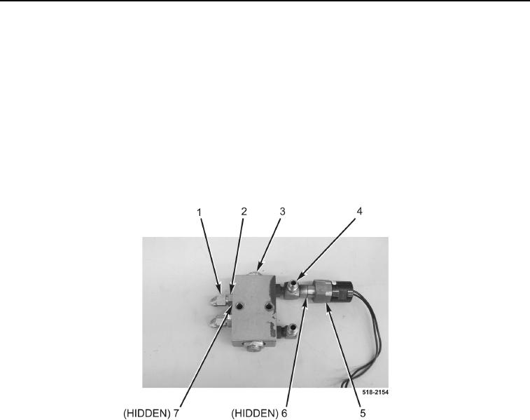
1. Install four new O-rings (Figure 5, Item 7) on fittings (Figure 5, Item 1), install fittings on load check valve
(Figure 5, Item 3), and tighten nuts (Figure 5, Item 2).
2. Install new O-ring (Figure 5, Item 6) and pressure switch (Figure 5, Item 5) on fitting (Figure 5, Item 4).
3. Repeat steps 1 and 2 on left-hand load check valve.
Figure 5. Fittings.
0239
END OF TASK