
TM 5-2420-231-23-3
0247
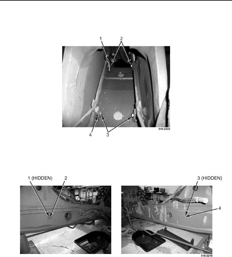
INSTALLATION CONTINUED
5. Install two bolts (Figure 8, Item 3) on rear clamps (Figure 8, Item 4).
6. Install two bolts (Figure 8, Item 2) on rear clamps (Figure 8, Item 1).
Figure 8. Rear Clamp Bolts.
0247
7. Install guard spacer (Figure 9, Item 1) on bolt (Figure 9, Item 2).
8. Install guard spacer (Figure 9, Item 3) on bolt (Figure 9, Item 4).
Figure 9. Guard Spacer.
0247