
TM 5-2420-231-23-3
0252
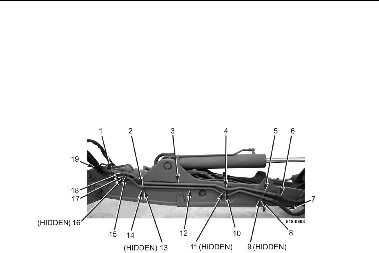
INSTALLATION CONTINUED
7. With assistance, position auxiliary hydraulic tubes on machine.
8. Install two clamps (Figure 3, Item 5), new locknuts (Figure 3, Item 8), and bolts (Figure 3, Item 9) on machine.
9. Install two clamps (Figure 3, Item 4), new locknut (Figure 3, Item 10), and bolt (Figure 3, Item 11) on machine.
10. Install clamp (Figure 3, Item 2), new locknut (Figure 3, Item 14), and bolt (Figure 3, Item 13) on machine.
11. Install spacer (Figure 3, Item 15), two clamps (Figure 3, Item 18), new locknut (Figure 3, Item 17), and bolt
(Figure 3, Item 16) on machine.
12. Connect auxiliary hydraulic hoses (Figure 3, Items 7 and 19) to auxiliary hydraulic tube (Figure 3, Item 12).
13. Connect auxiliary hydraulic hoses (Figure 3, Items 6 and 1) to auxiliary hydraulic tube (Figure 3, Item 3).
Figure 3. Auxiliary Hydraulic Tubes.
0252
14. Install cap on hydraulic tank (TM 5-2420-231-10).
END OF TASK
FOLLOW-ON TASKS
0252
Check hydraulic oil level and fill as necessary (TM 5-2420-231-10).
END OF TASK
END OF WORK PACKAGE