
TM 5-2420-231-23-3
0268
INSTALLATION CONTINUED
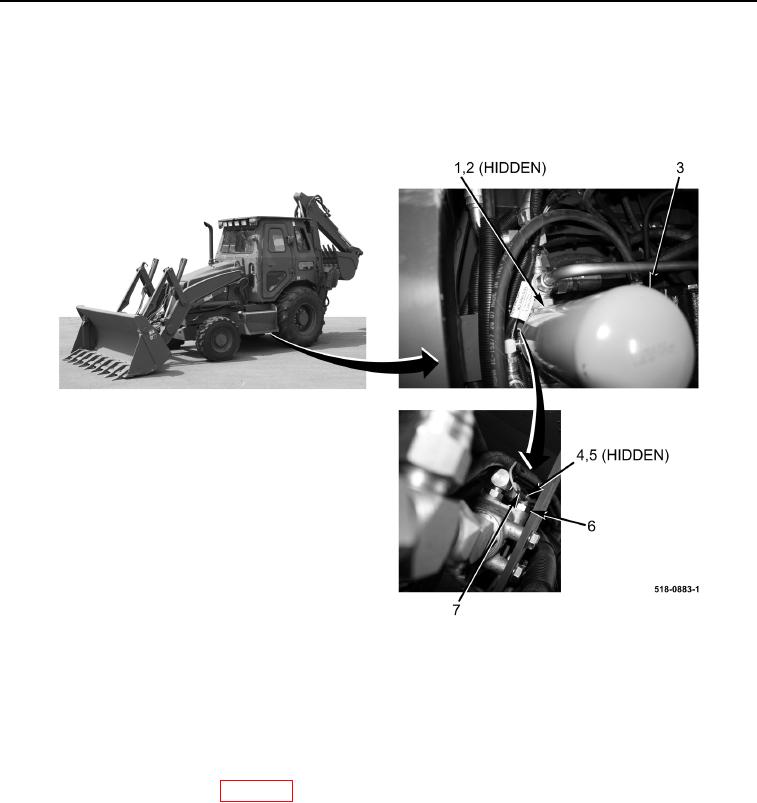
11. Install new gasket (Figure 5, Item 2) and hydraulic oil filter element (Figure 5, Item 3) on hydraulic oil filter
assembly (Figure 5, Item 1).
12. Connect main chassis wiring harness connector eyelet (Figure 5, Item 7) and install new lockwasher (Figure 5,
Item 5) and nut (Figure 5, Item 4) on hydraulic oil filter restriction switch (Figure 5, Item 6).
Figure 5. Hydraulic Oil Filter Restriction Switch.
0268
13. Install cap on hydraulic tank (TM 5-2420-231-10).
END OF TASK
FOLLOW-ON TASKS
0268
1. Install front floor cover plate (WP 0306).
2. Check hydraulic oil level and fill as necessary (TM 5-2420-231-10).
END OF TASK
END OF WORK PACKAGE
0268-7/(8 blank)