• Home
  • Download PDF
  • Order CD-ROM
  • Order in Print
Figure 3. Bellcrank Joint and Support Bracket.
Figure 6. Manual Control Lever.

Tractor, Wheeled, Industrial Backhoe Loader Nsn 2420-01-532-3399
Page Navigation
  386    387    388    389    390  391  392    393    394    395    396  
img
.
TM 5-2420-231-23-3
0277
REMOVAL CONTINUED
NOTE
Note the position and orientation of rods to aid in installation.
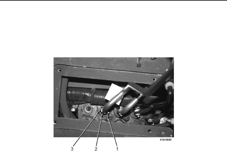
8. Remove three cotter pins (Figure 5, Item 1), clevis pins (Figure 5, Item 3), and rods (Figure 5, Item 2) from
machine. Discard cotter pins.
Figure 5. Rods.
0277
END OF TASK
0277-4


Privacy Statement
Press Release
Contact

© Copyright Integrated Publishing, Inc.. All Rights Reserved.