
TM 5-2420-231-23-3
0277
REMOVAL CONTINUED
NOTE
Note position and orientation of rods to aid in installation.
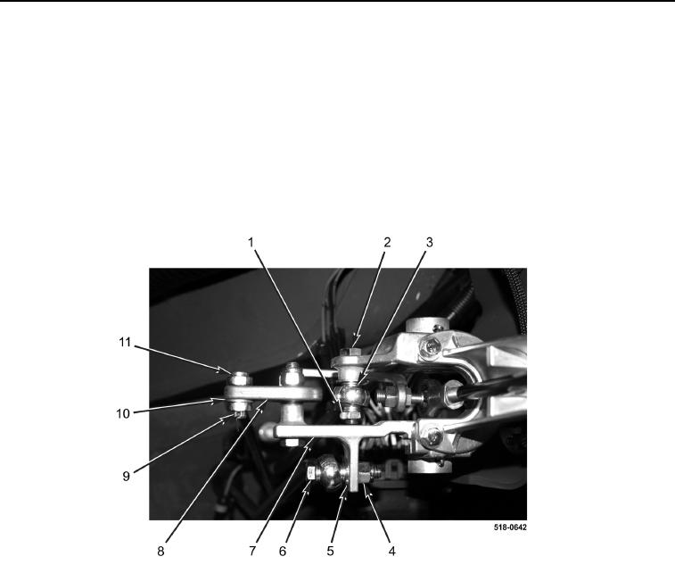
2. Remove bolt (Figure 2, Item 6), washer (Figure 2, Item 5), and locknut (Figure 2, Item 4) from bellcrank bracket
(Figure 2, Item 7). Discard locknut.
3. Remove cotter pin (Figure 2, Item 9), clevis pin (Figure 2, Item 11), and washer (Figure 2, Item 10) from rod
end (Figure 2, Item 8). Discard cotter pin.
4. Remove bolt (Figure 2, Item 2), nut (Figure 2, Item 1), and washer (Figure 2, Item 3) from bellcrank bracket
(Figure 2, Item 7).
Figure 2. Rod Fasteners.
0277