
TM 5-2420-231-23-3
0277
DISASSEMBLY CONTINUED
NOTE
Note location of rod bushing to aid in installation.
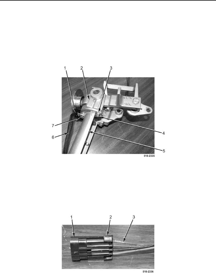
3. Remove two bolts (Figure 7, Item 4) and washers (Figure 7, Item 3) from manual control bracket
(Figure 7, Item 5).
4. Remove bolt (Figure 7, Item 7), clip (Figure 7, Item 1), wiring harness (Figure 7, Item 6), and manual control
bracket (Figure 7, Item 5) from linkage bracket (Figure 7, Item 2).
Figure 7. Linkage Bracket.
0277
5. Remove locking tab (Figure 8, Item 2) from connector (Figure 8, Item 1).
CAUTION
Tag and mark location of pins in the connector to aid in installation.
6. Remove four pins (Figure 8, Item 3) from connector (Figure 8, Item 1).
Figure 8. Connector.
0277