
TM 5-2420-231-23-3
0280
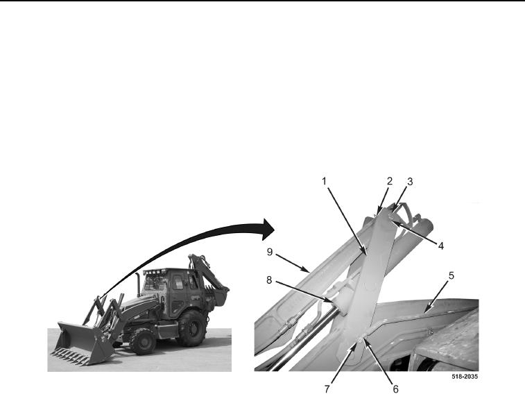
INSTALLATION CONTINUED
5. With assistance, install two mounting brackets (Figure 7, Item 1), four washers (Figure 7, Item 4), two bolts
(Figure 7, Item 3), and nuts (Figure 7, Item 2) on bucket cylinder (Figure 1, Item 8) and pitman arm
(Figure 7, Item 9).
NOTE
Step 6 applies to right-side loader linkage only.
6. Install self-leveling rod (Figure 7, Item 5), washer (Figure 7, Item 7), and E-clip (Figure 7, Item 6) on
mounting bracket (Figure 7, Item 1).
Figure 7. Self-Leveling Rod.
0280
END OF TASK
FOLLOW-ON TASKS
0280
Grease loader linkage (TM 5-2420-231-10).
END OF TASK
END OF WORK PACKAGE
0280-7/(8 blank)