
TM 5-2420-231-23-3
0280
REMOVAL
0280
NOTE
The procedure for loader linkage frame removal and replacement is identical for left-hand
and right-hand loader linkage frame. Right-hand loader linkage frame is shown in this
procedure.
Step 1 applies to right-side loader linkage only.
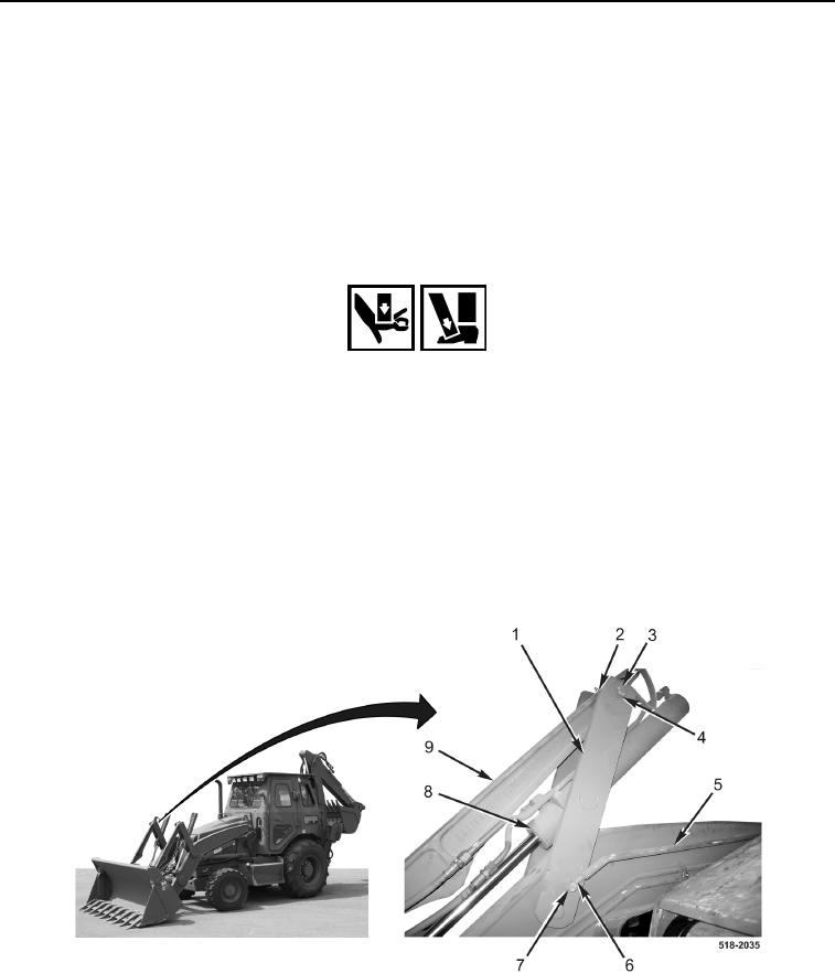
1. Remove E-clip (Figure 1, Item 6), washer (Figure 1, Item 7), and self-leveling rod (Figure 1, Item 5) from
mounting bracket (Figure 1, Item 1).
WARNING
Use extreme caution when handling heavy parts. Provide adequate support and use
assistance during procedure. Failure to follow this warning may result in injury or death to
personnel.
NOTE
Note position of mounting brackets to aid in installation.
2. Remove two bolts (Figure 1, Item 3), nuts (Figure 1, Item 2), and four washers (Figure 1, Item 4) from two
mounting brackets (Figure 1, Item 1).
3. With assistance, support bucket cylinder (Figure 1, Item 8) and pitman arm (Figure 1, Item 9) and remove two
mounting brackets (Figure 1, Item 1) from machine.
Figure 1. Mounting Brackets.
0280