
TM 5-2420-231-23-3
0281
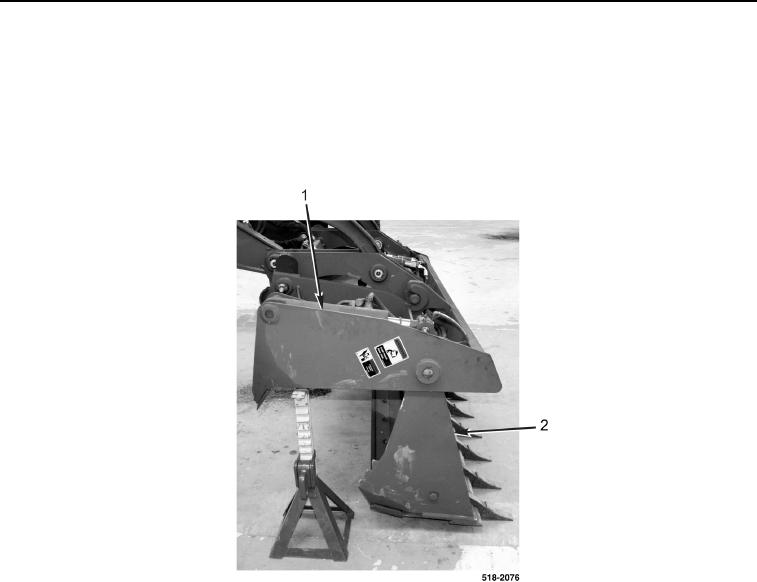
REMOVAL
0281
1. Turn on engine (TM 5-2420-231-10).
2. With assistance, position blade bucket (Figure 1, Item 1) downward with clam shell bucket (Figure 1, Item 2)
resting flat on ground.
3. Position two tressels under blade bucket (Figure 1, Item 1).
4. Turn engine off (TM-5-2420-231-10).
Figure 1. Bucket Assembly.
0281
NOTE
The procedure for loader clam removal and replacement is identical for left-hand and
right-hand loader clams. Left-hand loader clam is shown in this procedure.
Note location of bolts to aid in installation.
5. Remove locknut (Figure 2, Item 4), washer (Figure 2, Item 3), and bolt (Figure 2, Item 6) from pin (Figure 2,
Item 5). Discard locknut and bolt.
6. Remove pin (Figure 2, Item 5) from bucket assembly.
7. Remove locknut (Figure 2, Item 1) and bolt (Figure 2, Item 2) from pin (Figure 2, Item 7). Discard locknut and
bolt.
8. Remove pin (Figure 2, Item 7) from bucket assembly.