
TM 5-2420-231-23-3
0286
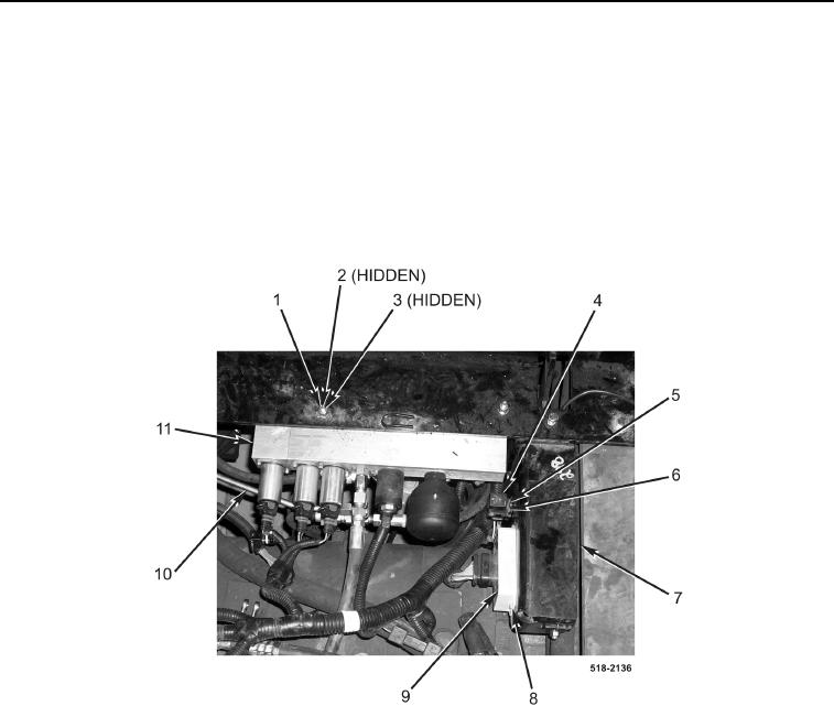
INSTALLATION CONTINUED
6. Position pilot control valve (Figure 23, Item 11) on machine, and install two bolts (Figure 23, Item 3), four wash-
ers (Figure 23, Item 2), and two new locknuts (Figure 23, Item 1) on pilot control valve (Figure 23, Item 11).
7. Position pilot control ECU (Figure 23, Item 9) on machine, and install two screws (Figure 23, Item 8) on pilot
control ECU and backhoe control tower bracket (Figure 23, Item 7).
8. Install relay connector (Figure 23, Item 6) and screw (Figure 23, Item 5) on backhoe control tower bracket
(Figure 23, Item 7).
9. Install relay (Figure 23, Item 4) on relay connector (Figure 23, Item 6).
10. Connect tube (Figure 23, Item 10) to pilot control valve (Figure 23, Item 11).
Figure 23. Pilot Control Valve.
0286