
TM 5-2420-231-23-3
0286
INSTALLATION
0286
NOTE
Install wires as tagged and marked during removal
Install lines as tagged and marked during removal.
Remove plugs and caps from hoses and fittings.
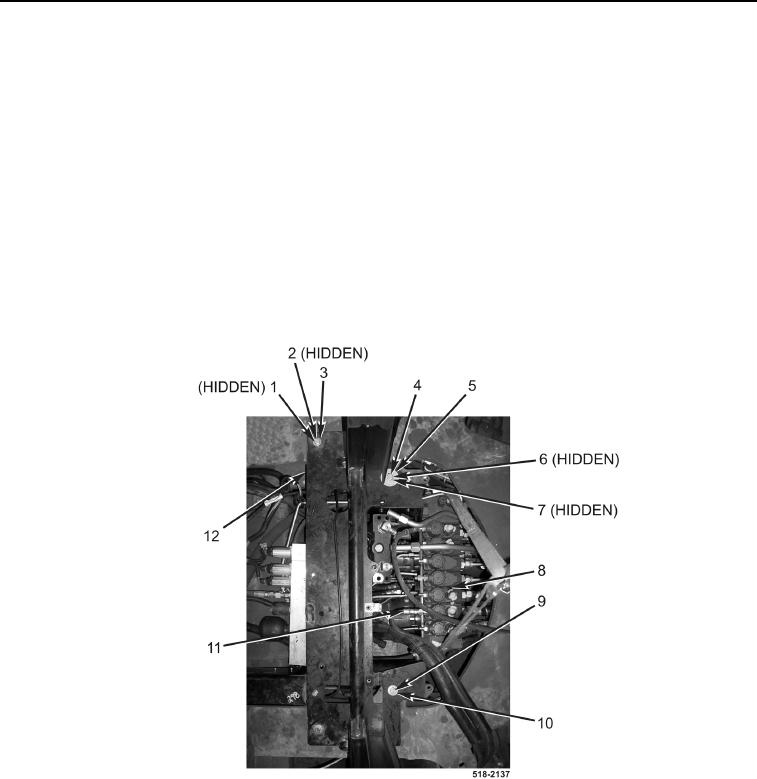
1. With assistance, position backhoe control tower (Figure 22, Item 12) on machine.
2. Install four washers (Figure 22, Item 2), two bolts (Figure 22, Item 1), and two new locknuts (Figure 22, Item 3)
on backhoe control tower (Figure 22, Item 12).
3. Install washer (Figure 22, Item 9) and bolt (Figure 22, Item 10) on backhoe control tower (Figure 22, Item 12).
4. Install spacer (Figure 22, Item 7), washer (Figure 22, Item 6), large washer (Figure 22, Item 5), and bolt
(Figure 22, Item 4) on backhoe control tower (Figure 22, Item 11).
5. Connect hose (Figure 22, Item 11) to backhoe control valve (Figure 22, Item 8).
Figure 22. Backhoe Tower.
0286