TM 5-2420-231-23-3
0286
ASSEMBLY CONTINUED
NOTE
Install piston rod as noted during removal.
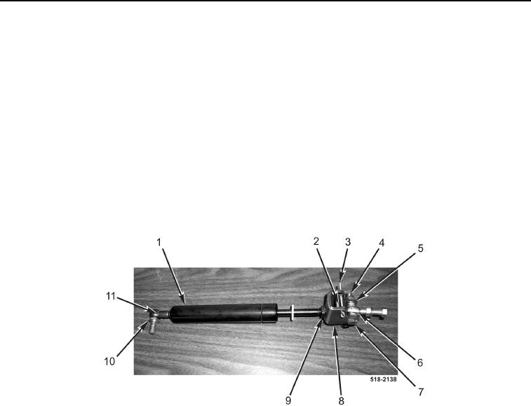
4. Install bracket (Figure 19, Item 8) on piston (Figure 19, Item 1), and tighten jamnut (Figure 19, Item 9).
NOTE
Install channel in position and orientation noted during removal.
5. Install channel (Figure 19, Item 2) and new cotter pin (Figure 19, Item 3) on bracket (Figure 19, Item 8).
6. Install pivot (Figure 19, Item 6), two spacers (Figure 19, Item 5), bolt (Figure 19, Item 7), and new locknut
(Figure 19, Item 4) on bracket (Figure 19, Item 8).
7. Install pivot (Figure 19, Item 10) and clip (Figure 19, Item 11) on piston (Figure 19, Item 1).
Figure 19. Backhoe Control Tower Piston.
0286
8. Position piston assembly (Figure 20, Item 12) on backhoe control tower (Figure 20, Item 4).
9. Connect spring (Figure 20, Item 8) to release bracket (Figure 20, Item 10) and backhoe control tower
(Figure 20, Item 4).
NOTE
Install bracket bolt as noted during removal.
10. Install new lockwasher (Figure 20, Item 6) and nut (Figure 20, Item 7) on piston bracket bolt
(Figure 20, Item 5).
NOTE
Route cable as noted during removal.
Adjust lock cable as noted during removal.
11. Position cable (Figure 20, Item 1) on backhoe control tower (Figure 20, Item 4), and connect cable to release
bracket (Figure 20, Item 10).
12. Install new cotter pin (Figure 20, Item 9) on cable (Figure 20, Item 1) and release bracket (Figure 20, Item 10).

