
TM 5-2420-231-23-3
0286
INSTALLATION CONTINUED
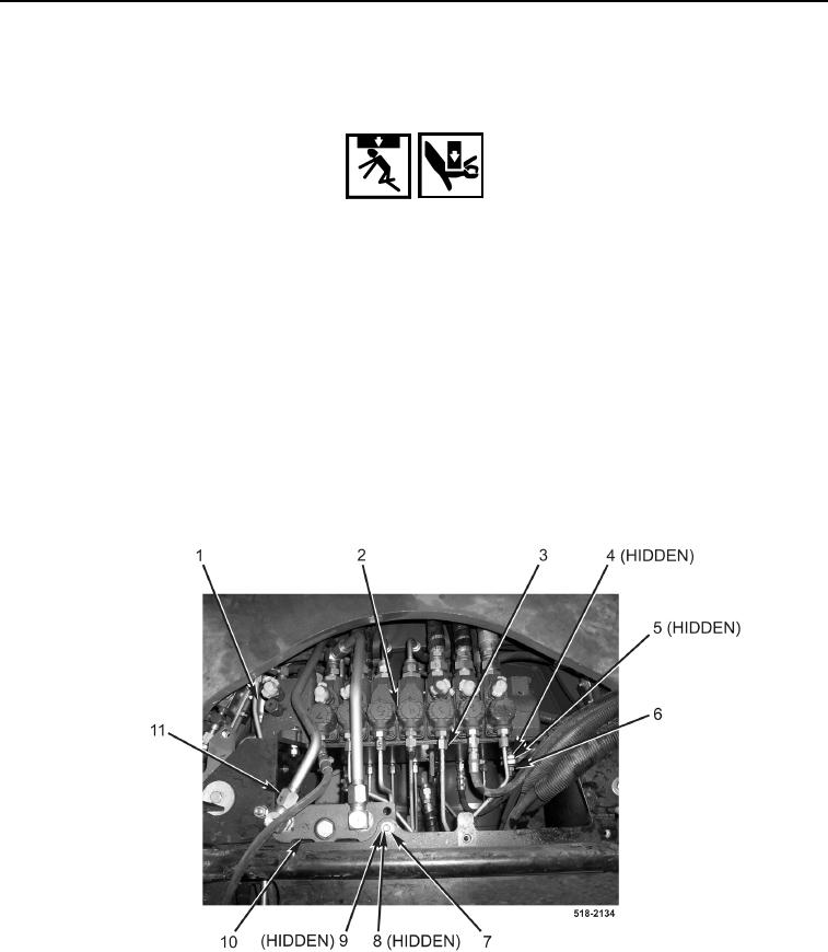
15. Position backhoe swing valve (Figure 25, Item 10) on machine, and install two bolts (Figure 25, Item 9), four
washers (Figure 25, Item 8), and two nuts (Figure 25, Item 7) on backhoe swing valve.
WARNING
Use extreme caution when handling heavy parts. Provide adequate support and use
assistance during procedure. Ensure any lifting device used is in good condition and of
suitable load capacity. Keep clear of heavy parts supported only by lifting device. Failure to
follow this warning may result in injury or death to personnel.
NOTE
Backhoe control valve assembly weighs 125 lb (57 kg).
16. Support backhoe control valve (Figure 25, Item 2) with nylon strap and lifting device.
17. Install six washers (Figure 25, Item 5), three bolts (Figure 25, Item 4), and nuts (Figure 25, Item 6) on backhoe
control valve (Figure 25, Item 2).
18. Connect two steel tubes (Figure 25, Item 11) to backhoe swing valve (Figure 25, Item 10)
19. Connect ten steel tubes (Figure 25, Item 3) to backhoe control valve (Figure 25, Item 2).
20. Connect steel tube (Figure 25, Item 1) to backhoe control valve (Figure 25, Item 2).
Figure 25. Backhoe Control Valve.
0286