
TM 5-2420-231-23-3
0286
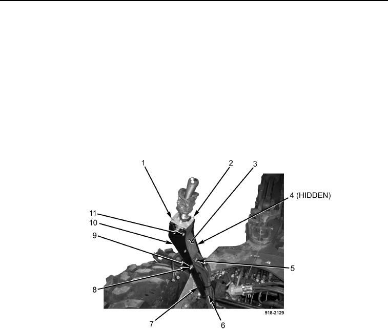
INSTALLATION CONTINUED
28. Position joystick plate (Figure 29, Item 2) in right joystick bracket (Figure 29, Item 10).
29. With assistance, install right joystick bracket (Figure 29, Item 10), spacer (Figure 29, Item 5), two washers
(Figure 29, Item 9), bolt (Figure 29, Item 4), and new locknut (Figure 29, Item 8) on right backhoe control tower
(Figure 1, Item 7).
30. Install plate (Figure 29, Item 3) and four bolts (Figure 29, Item 11) on joystick bracket (Figure 29, Item 10).
31. Install two bolts (Figure 29, Item 1) on joystick plate (Figure 29, Item 2).
NOTE
Install tiedown straps as noted during removal.
32. Install tiedown strap (Figure 29, Item 6) on right backhoe control tower (Figure 29, Item 7).
Figure 29. Right Tower.
0286