
TM 5-2420-231-23-3
0286
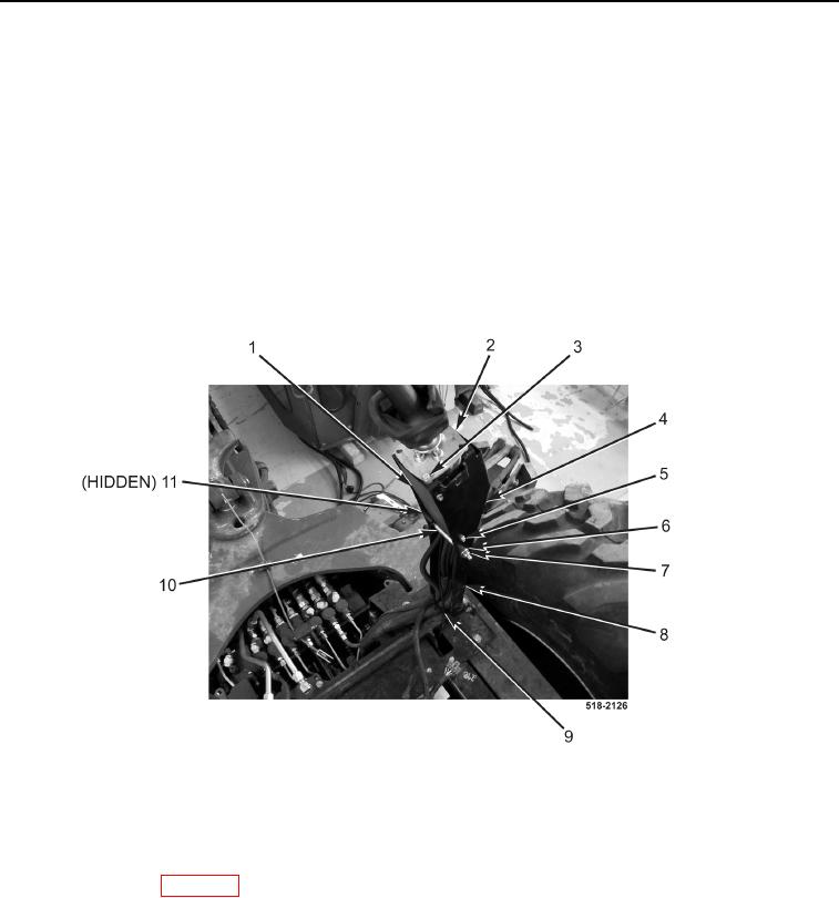
INSTALLATION CONTINUED
37. Position joystick plate (Figure 32, Item 2) in left joystick bracket (Figure 32, Item 4).
38. With assistance, install left joystick bracket (Figure 32, Item 4), spacer (Figure 32, Item 10), two washers
(Figure 32, Item 6), bolt (Figure 32, Item 11), and new locknut (Figure 32, Item 7) on left backhoe control tower
(Figure 32, Item 8).
39. Install plate (Figure 32, Item 1) and four bolts (Figure 32, Item 5) on joystick bracket (Figure 32, Item 4).
40. Install two bolts (Figure 32, Item 3) on joystick plate (Figure 32, Item 2).
NOTE
Install tiedown straps as noted during removal.
41. Install tiedown strap (Figure 32, Item 9) on left backhoe control tower (Figure 32, Item 8).
Figure 32. Left Tower.
0286
END OF TASK
FOLLOW-ON TASKS
0286
Install cab assembly (WP 0327).
END OF TASK
END OF WORK PACKAGE
0286-31/(32 blank)