
TM 5-2420-231-23-3
0286
INSTALLATION CONTINUED
NOTE
Adjust cable as noted during removal.
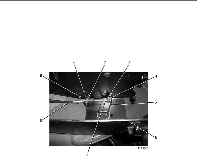
34. Position joystick bracket (Figure 31, Item 6) on machine.
35. Install cable (Figure 31, Item 8) on mount (Figure 31, Item 1), and tighten jamnut (Figure 31, Items 9 and 2).
36. Connect cable end (Figure 31, Item 7) to lever (Figure 31, Item 5), and install bolt (Figure 31, Item 3) and new
locknut (Figure 31, Item 4) on lever (Figure 31, Item 5).
Figure 31. Adjustment Cable.
0286