
10
TM 5-2420-231-23-3
FIELD MAINTENANCE
-
CHASSIS MOUNTS REPLACEMENT
0300
Rear Chassis Mounts Removal, Front Chassis Mounts Removal, Cleaning and Inspection, Front Chassis
Mounts Installation, Rear Chassis Mounts Installation
INITIAL SETUP
Personnel Required
Tools and Special Tools
Tool Kit, General Mechanic's
Two
0
0
(WP 0376, Item 117)
References
Bracket, Link (WP 0376, Item 6) (2)
0
Chain, Chain Hoist, 9/32", Wll 3,500-lb, L 11-1/
0
0
WP 0374 (Group Number 0820)
2" SGG (WP 0376, Item 11)
0
Socket, Standard, Impact, 1/2" Dr., Metric, 6 Pt,
Equipment Conditions
0
24 mm (WP 0376, Item 101)
Machine parked (TM 5-2420-231-10)
0
Lifting Device (5,000-lb capacity)
0
Estimated Time to Complete
Materials/Parts
1.5 hr
0
Rag, Wiping (WP 0375, Item 25)
0
REAR CHASSIS MOUNTS REMOVAL
0300
NOTE
The procedure for rear bracket link installation is identical for left-hand and right-hand rear
bracket links. Left-hand rear bracket link is shown in this procedure.
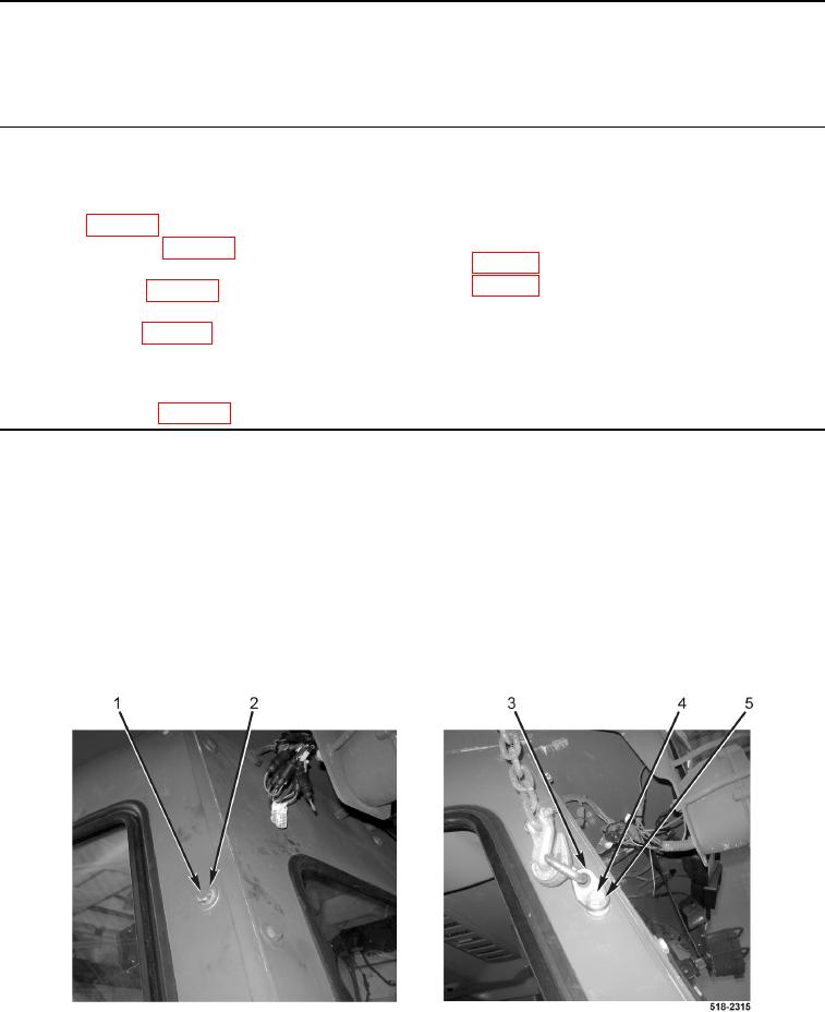
1. Remove bolt (Figure 1, Item 1) and washer (Figure 1, Item 2) from cab.
2. Install bracket link (Figure 1, Item 3), washer (Figure 1, Item 5), and bolt (Figure 1, Item 4) on cab.
3. Repeat steps 1 and 2 for right-hand rear bracket link.
4. Attach two lift chains and lifting device to two bracket links.
Figure 1. Bracket Links.
0300