
TM 5-2420-231-23-3
0302
ASSEMBLY CONTINUED
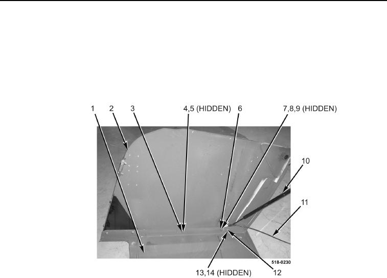
4. Install right-side panel (Figure 12, Item 2), three bolts (Figure 12, Item 3), washers (Figure 12, Item 4), and nuts
(Figure 12, Item 5) on hood (Figure 12, Item 1).
5. Install shock absorber (Figure 12, Item 10), shock absorber pivot (Figure 12, Item 14), washer (Figure 12,
Item 13), and nut (Figure 12, Item 12) on hood (Figure 12, Item 1).
6. Install washer (Figure 12, Item 7), bolt (Figure 12, Item 6), spacer (Figure 12, Item 8), cable (Figure 12,
Item 11), and nut (Figure 12, Item 9) on hood (Figure 12, Item 1).
Figure 12. Right-Side Panel.
0302