
TM 5-2420-231-23-3
0302
DISASSEMBLY CONTINUED
NOTE
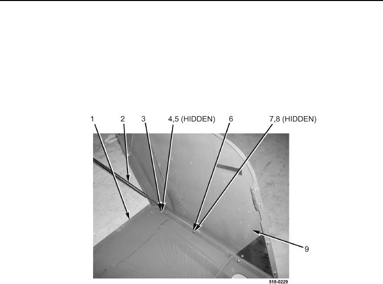
Mark the position of the hood side panels in relation to the hood to aid in installation.
5. Remove nut (Figure 9, Item 3), washer (Figure 9, Item 4), shock absorber pivot (Figure 9, Item 5), and shock
absorber (Figure 9, Item 2) from hood (Figure 9, Item 1).
6. Remove four nuts (Figure 9, Item 8), washers (Figure 9, Item 7), bolts (Figure 9, Item 6), and left-side panel
(Figure 9, Item 9) from hood (Figure 9, Item 1).
Figure 9. Left-Side Panel.
0302