
TM 5-2420-231-23-3
0302
DISASSEMBLY CONTINUED
NOTE
Note orientation of locking tab nut to aid in assembly.
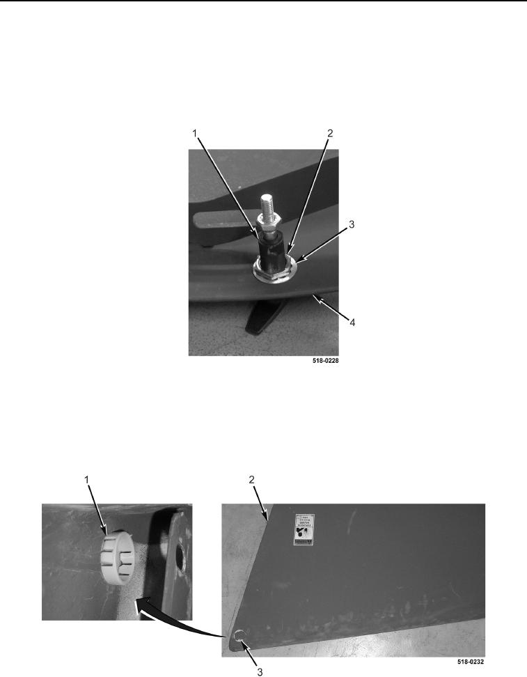
3. Remove nut (Figure 7, Item 2), lockwasher (Figure 7, Item 3), and hood lock (Figure 7, Item 1) from hood
(Figure 7, Item 4). Discard lockwasher.
Figure 7. Hood Lock.
0302
NOTE
The procedure for plug removal and replacement is identical for left-hand and right-hand
plugs. Left-hand plug is shown in this procedure.
4. Compress tabs (Figure 8, Item 1) and remove two plugs (Figure 8, Item 3) from side panels (Figure 8, Item 2).
Figure 8. Plug.
0302