
TM 5-3805-255-14
0028
REMOVAL CONTINUED
NOTE
There are helical gears on pump and pinion shaft, and in order for pump to be removed or
installed, one or both of these gears has to rotate. Capscrews are loosened to permit shaft
to rotate within limits of elongated holes in drive gear.
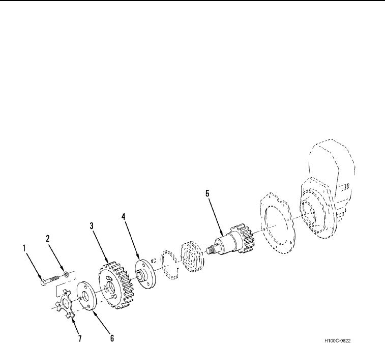
If capscrews (Figure 2, Item 1) are secured with a lock plate (Figure 2, Item 7), lock plate
and retainer plate (Figure 2, Item 6) should not be reused. Replace with three washers
(Figure 2, Item 2).
4. Loosen three timing pointer capscrews (Figure 2, Item 1) securing drive gear (Figure 2, Item 3) to hub
(Figure 2, Item 4) on pinion shaft (Figure 2, Item 5).
Figure 2. Exploded View of Injection Pump Adapter.
0028
0028-3