
TM 5-3805-255-14
0028
REMOVAL CONTINUED
NOTE
Air cleaner dust unloader is located right above injection pump. Be sure to clean this out
before disconnecting any lines to prevent dirt from unloading into pump openings.
Cap and tag all openings of pump and lines immediately after disconnecting to prevent
entry of dirt.
Place a suitable drain pan under fuel injection pump to catch fuel as lines are
disconnected.
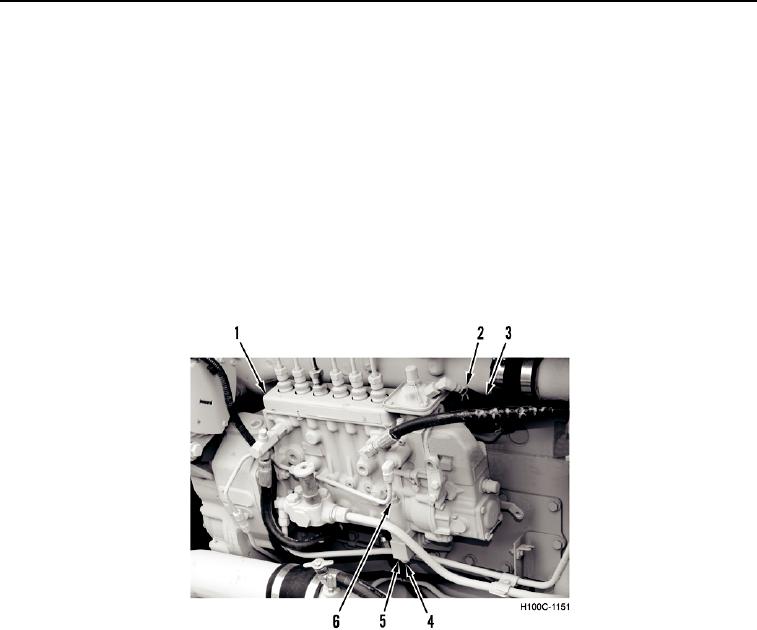
5. Remove clamp (Figure 3, Item 2) and disconnect hose (Figure 3, Item 3) from fuel injection pump (Figure 3,
Item 1).
6. Remove nut (Figure 3, Item 6), bolt (Figure 3, Item 4), and washer (Figure 3, Item 5) from fuel injection pump
(Figure 3, Item 1).
Figure 3. Fuel Injection Pump Cables.
0028
0028-4