
TM 5-3805-255-14
0028
INSTALLATION CONTINUED
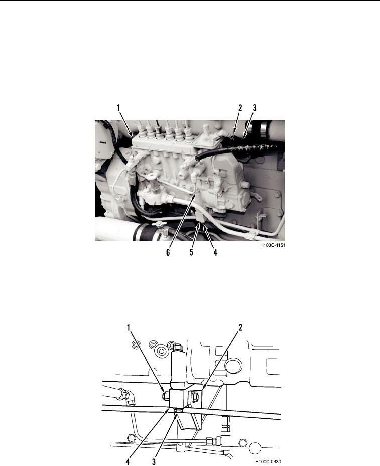
10. Install bolt (Figure 6, Item 4), washer (Figure 6, Item 5), and nut (Figure 6, Item 6) on fuel injection pump
(Figure 6, Item 1).
NOTE
Install hose as noted during removal.
11. Connect hose (Figure 6, Item 3) to fuel injection pump (Figure 6, Item 1). Position clamp (Figure 8, Item 2).
Figure 6. Fuel Injection Pump Cables.
0028
12. With three capscrews loosely installed, remove pivot bracket capscrew (Figure 7, Item 1). Adjust support
(Figure 7, Item 4) and bracket (Figure 7, Item 2) so that with these parts tightened, pivot capscrew (Figure 7,
Item 3) can be inserted freely through bracket and support. Install pivot capscrew and pivot bracket capscrew.
Figure 7. Injection Pump Adjustable Support with Bracket.
0028
0028-7