TM 5-3805-255-14
0028
INSTALLATION CONTINUED
NOTE
Remove plug located on top of injection pump adapter housing so that injection pump
gear is visible for timing procedure.
13. Rotate drive gear to bring mark on injection pump gear into alignment with pointer on pump and tighten three
drive gear capscrews evenly.
14. Rotate engine crankshaft counterclockwise (as viewed from fan drive end) to approximately 60 degrees before
top dead center of No. 1 cylinder and bring it back clockwise to 38 degrees BTDC.
15. Check timing pointer to be sure it lines up with mark on gear. If pointer is not aligned, loosen capscrews on
drive gear and align. Tighten capscrews.
16. Install plug on pump adapter housing.
17. Secure injection pump timing cover to crankcase front cover.
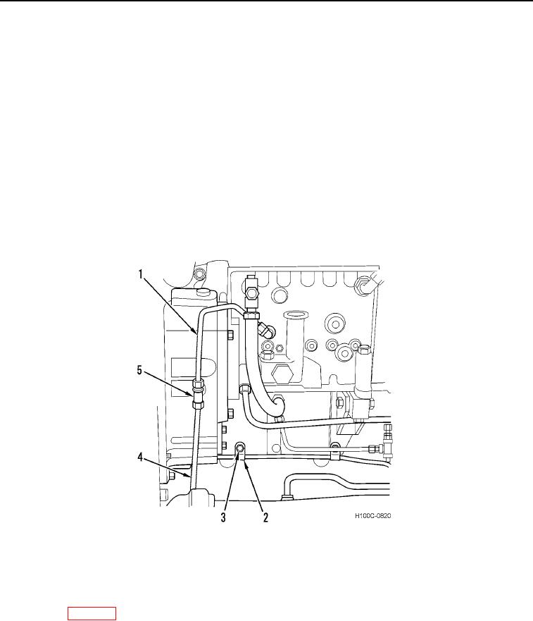
18. Connect tube (Figure 8, Item 1) to tee (Figure 8, Item 5). Secure two clips (Figure 8, Item 2) to crankcase with
capscrews (Figure 8, Item 3).
19. Connect tube (Figure 8, Item 4) to tee (Figure 8, Item 5).
Figure 8. Fittings and Clamps.
0028
20. Ensure control linkage is properly adjusted.
NOTE
Fuel system may need priming. If fuel does not flow from lines while cranking engine, refer
to WP 0018.
21. With control lever positioned in half throttle position, crank engine (at 10-second intervals) until fuel flows from
all six loose fuel line nuts. Torque line nuts at pump to 30 lb-ft (40 Nm).
22. Start engine and verify all connections made do not leak.
END OF TASK
0028-8

