
TM 5-3805-255-14
0044
INSTALLATION CONTINUED
Water Temperature Sending Unit
00044
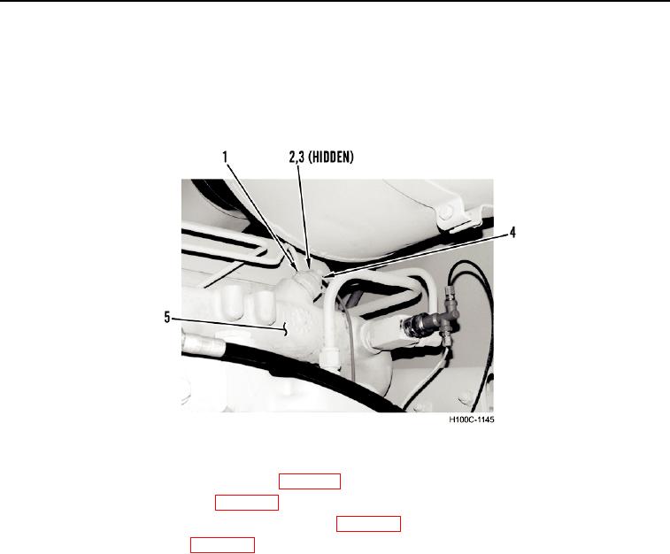
1. Install water temperature sending unit (Figure 5, Item 1) in water manifold (Figure 5, Item 5).
2. Install wire eyelet (Figure 5, Item 4), washer (Figure 5, Item 3), and nut (Figure 5, Item 2) on water temperature
sending unit (Figure 5, Item 1).
Figure 5. Water Temperature Sending Unit.
044
3. Check and fill engine coolant as necessary (WP 0018).
4. Start engine and check for leaks (WP 0005).
5. Check water temperature gauge for proper operation (WP 0005).
6. Install engine access panels (WP 0005).
0044-7