
TM 5-3805-255-14
0044
REMOVAL CONTINUED
Oil Pressure Sending Unit
00044
NOTE
There are two oil pressure sending units, one for high oil pressure and one for low oil
pressure.
Tag and identify all wires to aid in installation.
1. Place suitable container under engine to catch oil as sending units are removed.
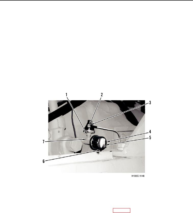
2. Remove screw (Figure 3, Item 2) and wire eyelet (Figure 3, Item 3) from oil pressure sending unit (Figure 3,
Item 1).
3. Remove oil pressure sending unit (Figure 3, Item 1) from fitting (Figure 3, Item 7).
4. Remove nut (Figure 3, Item 5) and wire eyelet (Figure 3, Item 6) from oil pressure sending unit (Figure 3,
Item 4).
5. Remove oil pressure sending unit (Figure 3, Item 4) from fitting (Figure 3, Item 7).
Figure 3. Oil Pressure Sending Unit.
044
END OF TASK
CLEANING AND INSPECTION
0044
Clean and inspect all parts IAW General Maintenance Instructions (WP 0019).
END OF TASK
0044-5