
TM 5-3805-255-14
0045
REMOVAL CONTINUED
00045
6VDC Batteries
00045
1. Open battery cover.
NOTE
Tag and identify battery cables to aid in installation.
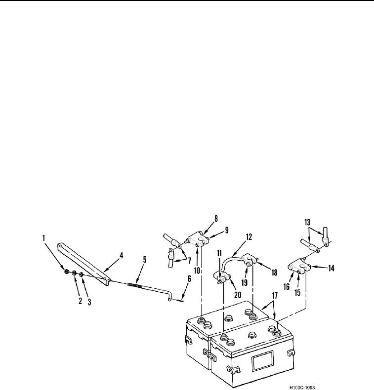
2. Remove nut (Figure 2, Item 9), bolt (Figure 2, Item 10), two positive cables (Figure 2, Item 7), and cable end
(Figure 2, Item 8) from positive battery terminal.
3. Remove nut (Figure 2, Item 14), bolt (Figure 2, Item 15), two negative cables (Figure 2, Item 13), and cable
end (Figure 2, Item 16) from negative battery terminal.
4. Remove two nuts (Figure 2, Items 18 and 11), bolts (Figure 2, Items 19 and 20), and intermediate cable (Figure
1, Item 12) from battery terminals.
5. Remove two cotter pins (Figure 2, Item 6) from angle bolts (Figure 2, Item 5). Discard cotter pins.
6. Remove two nuts (Figure 2, Item 1), washers (Figure 2, Item 2), lockwashers (Figure 2, Item 3), battery hold-
downs (Figure 2, Item 4), and angle bolts (Figure 2, Item 5).
7. Remove two batteries (Figure 2, Item 17) from loader.
8. Repeat steps 1 through 7 for batteries on the opposite side of loader.
Figure 2. 6VDC Batteries.
0045
END OF TASK
0045-4