
TM 5-3805-255-14
0045
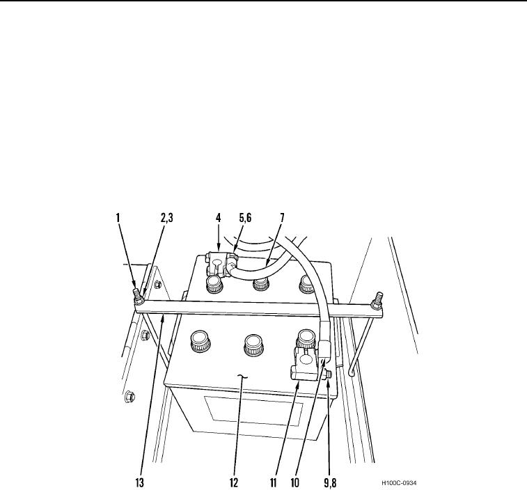
INSTALLATION CONTINUED
00045
12VDC Batteries
00045
1. Install battery (Figure 3, Item 12) in vehicle.
2. Install positive cable (Figure 3, Item 10), terminal (Figure 3, Item 11), bolt (Figure 3, Item 9), and nut (Figure 3,
Item 8) on battery terminal.
3. Install negative cable (Figure 3, Item 7), terminal (Figure 3, Item 4), bolt (Figure 3, Item 6), and nut (Figure 3,
Item 5) on battery terminal.
4. Install two angle bolts (Figure 3, Item 1), battery hold-down (Figure 4, Item 13), two washers (Figure 3, Item 3),
and nuts (Figure 3, Item 2) on loader.
5. Close battery cover.
6. Repeat steps 1 through 5 for battery on opposite side of loader.
Figure 3. 12VDC Battery.
0045
END OF TASK
END OF WORK PACKAGE
0045-6