
TM 5-3805-255-14
0046
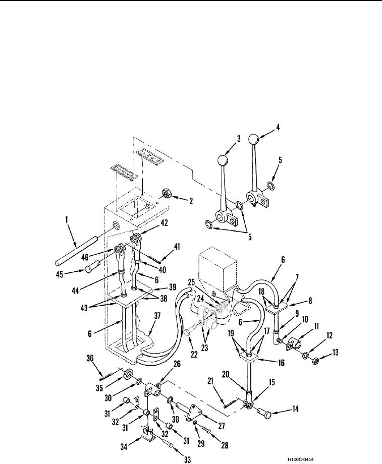
REMOVAL CONTINUED
19. Remove self-locking nut (Figure 1, Item 2), pivot pin (Figure 1, Item 1), two control levers (Figure 1, Items 3
and 4), and three O-rings (Figure 1, Item 5) from control housing (Figure 1, Item 39). Discard self-locking nut
and O-rings.
20. Remove three bolts (Figure 1, Item 28) and washers (Figure 1, Item 29) from support shaft (Figure 1, Item 27).
21. Remove cotter pin (Figure 1, Item 36), washer (Figure 1, Item 35), clevis pin (Figure 1, Item 33), two O-rings
(Figure 1, Item 30), support shaft (Figure 1, Item 27), bellcrank (Figure 1, Item 26), and three bushings (Figure
1, Item 31) from two links (Figure 1, Item 32) and transmission (Figure 1, Item 34). Discard cotter pin and two
O-rings.
Figure 1. Transmission Control Linkage.
0046
END OF TASK
0046-3