TM 5-3805-255-14
0046
ADJUSTMENT
00046
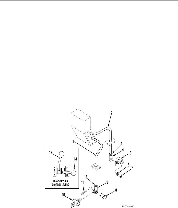
1. Remove nut (Figure 3, Item 7) and lockwasher (Figure 3, Item 6) from ball joint (Figure 3, Item 4) on end of
range control lever control cable (Figure 3, Item 2). Discard lockwasher.
2. Remove ball joint (Figure 3, Item 4) from range bellcrank (Figure 3, Item 5).
3. Remove cotter pin (Figure 3, Item 11) and clevis pin (Figure 3, Item 8) from directional control cable clevis
(Figure 3, Item 9). Discard cotter pin.
4. Remove cable clevis (Figure 3, Item 9) from directional bellcrank (Figure 3, Item 10).
5. Position directional control lever (Figure 3, Item 14) in "NEUTRAL" and range control lever (Figure 3, Item 13)
in "1". Block or otherwise immobilize both levers in these positions until adjustments are completed.
6. Position range bellcrank (Figure 3, Item 5) in its uppermost position.
7. Loosen locknut (Figure 3, Item 3), adjust ball joint (Figure 3, Item 4) so it freely fits bore of range bellcrank
(Figure 3, Item 5), and install new lockwasher (Figure 3, Item 6) and nut (Figure 3, Item 7).
8. Position directional bellcrank (Figure 3, Item 10) in center position. Adjust cable clevis (Figure 3, Item 9) so that
clevis bore aligns with bore of bellcrank arm.
9. Install clevis pin (Figure 3, Item 8) on cable clevis (Figure 3, Item 9).
10. Install new cotter pin (Figure 3, Item 11) on clevis pin (Figure 3, Item 8).
11. Remove lever blocking and start engine. Operate loader throughout full range of speeds in both forward and
reverse. Check for positive action of levers and correct positioning of transmission spools.
12. When adjustments are satisfactorily completed, shut off engine, tighten all locknuts (Figure 3, Items 3, 12,
and 7), and bend over cotter pin (Figure 3, Item 11).
Figure 3. Transmission Control Linkage Adjustment.
0046
END OF TASK
END OF WORK PACKAGE
0046-6

