
TM 5-3805-255-14
0049
ASSEMBLY CONTINUED
00049
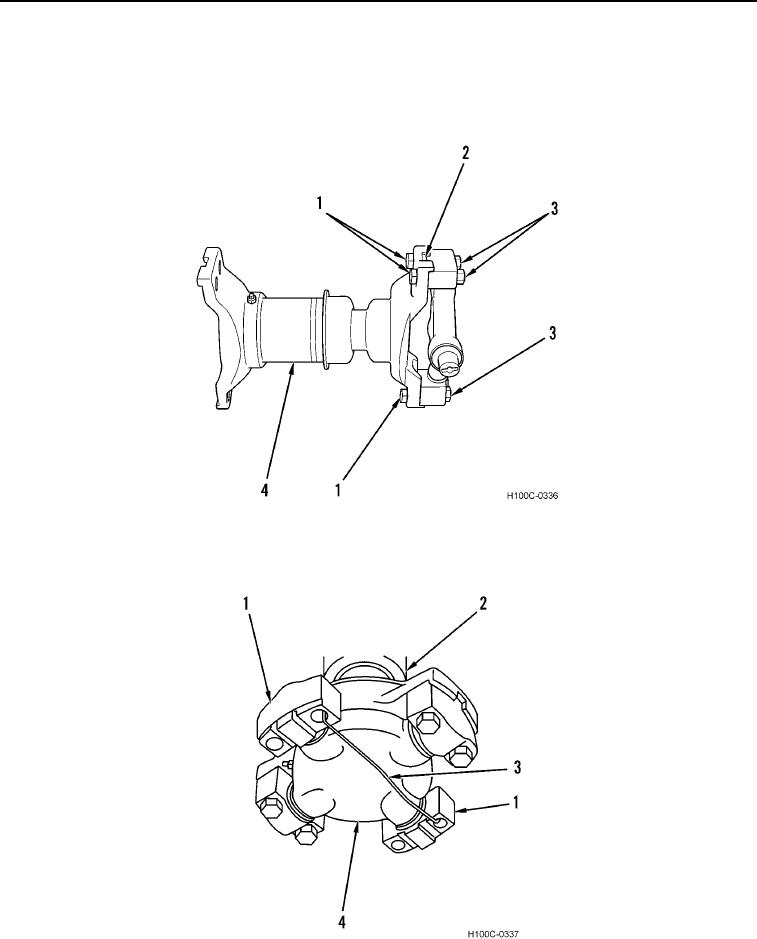
5. Install four capscrews (Figure 6, Item 1) and four new locknuts (Figure 6, Item 3) in bearing caps (Figure 6,
Item 2). Torque capscrews and locknuts to 40 to 50 lb-ft (54 to 68 Nm) on torque-converter-to-transmission
propeller shaft (Figure 6, Item 4). For all other propeller shafts, torque hardware to 90 to 100 lb-ft (122 to 136
Nm).
Figure 6. Spider Fastener Installation.
0049
6. Install remaining two bearings (Figure 7, Item 1) on spider (Figure 7, Item 4). Use mechanic's wire (Figure 7,
Item 3) to secure spider to propeller shaft.
Figure 7. Bearing Cap Wire Installation.
0049
END OF TASK
0049-6