• Home
  • Download PDF
  • Order CD-ROM
  • Order in Print
Figure 4. Propeller Shaft Assembly.
Figure 7. Bearing Cap Wire Installation.

Maintenance Manual For Loader, Scoop Type, Ded 4 X 4, Articulated Frame Steer, 4.5 To 5 Cu. Yd.
Page Navigation
  448    449    450    451    452  453  454    455    456    457    458  
img
TM 5-3805-255-14
0049
ASSEMBLY CONTINUED
00049
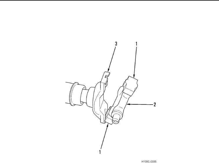
3. Install two opposite bearing caps (Figure 5, Item 1) onto spider (Figure 5, Item 2).
4. Insert bearing cap (Figure 5, Item 1) into groove in yoke (Figure 5, Item 3) and install spider (Figure 5, Item 2)
in yoke (Figure 5, Item 3). Tap opposite bearing cap at an angle to seat spider and bearing assembly.
Figure 5. Spider Installation.
0049
0049-5


Privacy Statement
Press Release
Contact

© Copyright Integrated Publishing, Inc.. All Rights Reserved.