• Home
  • Download PDF
  • Order CD-ROM
  • Order in Print
Figure 6. Air Cylinder.
Figure 9. Hydraulic Cylinder Disassembly.

Maintenance Manual For Loader, Scoop Type, Ded 4 X 4, Articulated Frame Steer, 4.5 To 5 Cu. Yd.
Page Navigation
  530    531    532    533    534  535  536    537    538    539    540  
img
TM 5-3805-255-14
0060
DISASSEMBLY CONTINUED
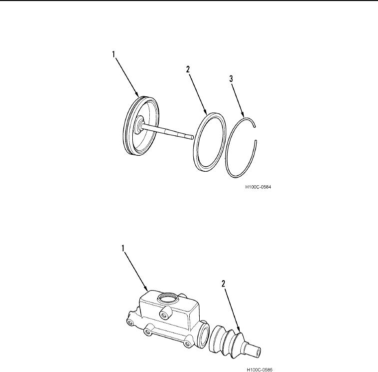
8. Remove air cylinder piston cup (Figure 7, Item 2) and wiper (Figure 7, Item 3) from piston (Figure 7, Item 1).
Figure 7. Piston Cup.
060
9. Separate piston rod boot (Figure 7, Item 2) from hydraulic cylinder (Figure 7, Item 1).
Figure 8. Rod Boot.
060
0060-6


Privacy Statement
Press Release
Contact

© Copyright Integrated Publishing, Inc.. All Rights Reserved.