TM 5-3805-255-14
0060
DISASSEMBLY CONTINUED
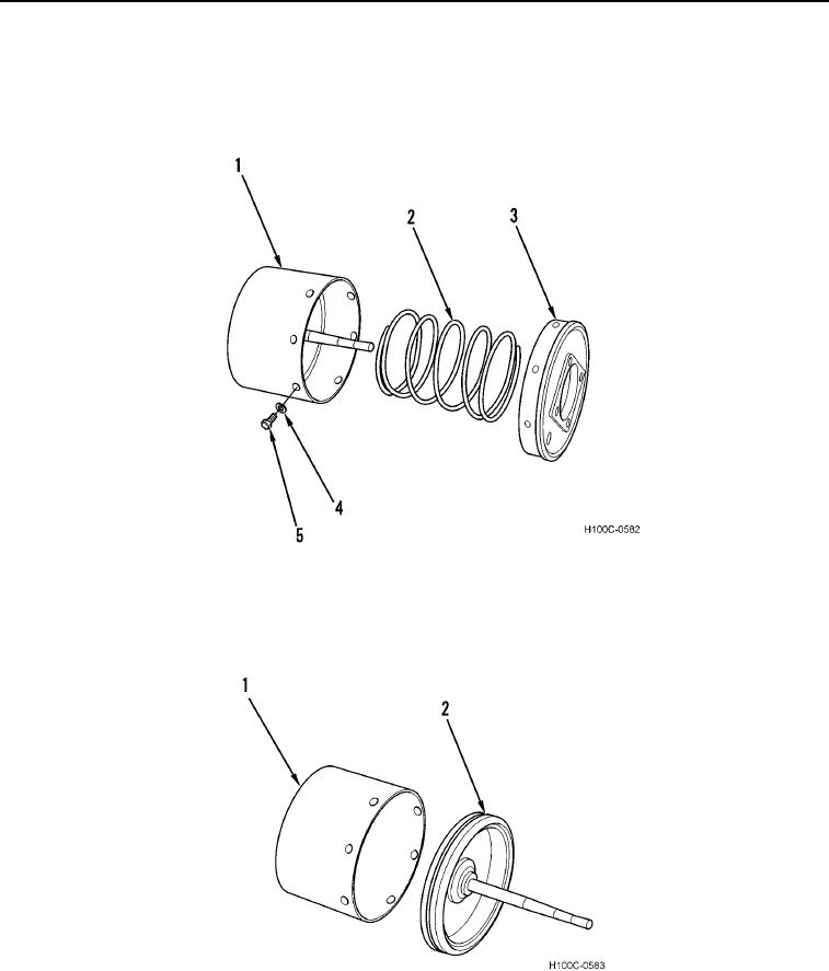
5. Remove six bolts (Figure 5, Item 5), lockwashers (Figure 5, Item 4), air cylinder shell (Figure 5, Item 1), and
piston return spring (Figure 5, Item 2) from head (Figure 5, Item 3). Discard lockwashers.
6. Remove indicator rod and return spring, and unscrew breather from face of head, if equipped.
Figure 5. Return Spring.
060
7. Remove piston and rod assembly (Figure 6, Item 2) from air cylinder shell (Figure 6, Item 1).
Figure 6. Air Cylinder.
060
0060-5

