
TM 5-3805-255-14
0072
REMOVAL CONTINUED
00072
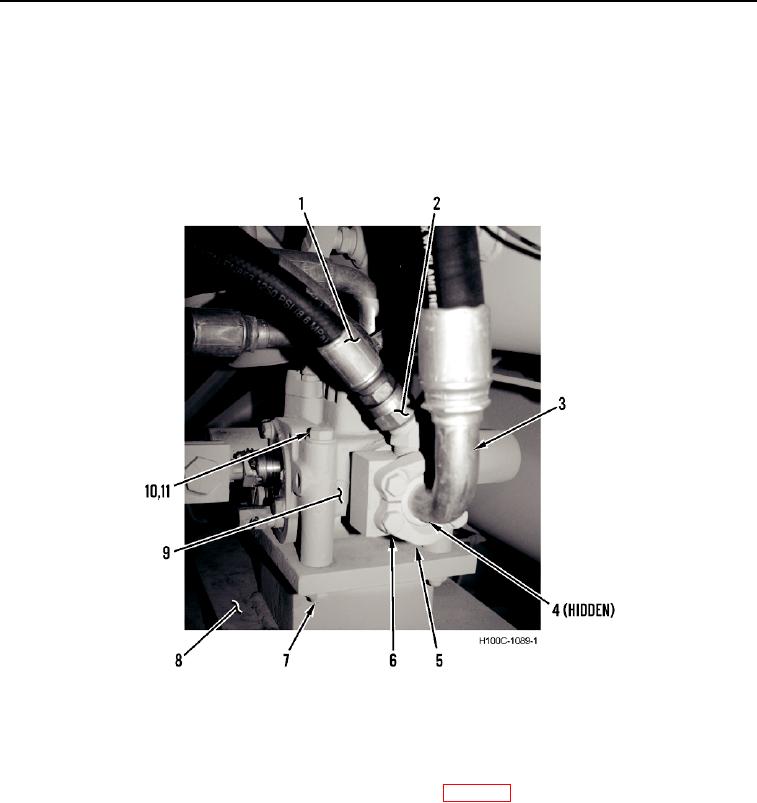
3. Loosen fitting (Figure 2, Item 2), and disconnect hydraulic line (Figure 2, Item 1) from steering control valve
(Figure 2, Item 9).
4. Remove four bolts (Figure 2, Item 6), two split flanges (Figure 2, Item 5), hydraulic line (Figure 2, Item 3) and
O-ring (Figure 2, Item 4) from steering control valve (Figure 2, Item 9). Discard O-ring.
5. Remove three bolts (Figure 2, Item 10), nuts (Figure 2, Item 7), six washers (Figure 2, Item 11), and steering
control valve (Figure 2, Item 9) from frame (Figure 2, Item 8).
Figure 2. Steering Control Valve, Right Side.
0072
END OF TASK
CLEANING AND INSPECTION
00072
Clean and inspect all parts IAW General Maintenance Instructions (WP 0019).
END OF TASK
0072-3