
TM 5-3805-255-14
0072
INSTALLATION
00072
NOTE
Remove caps and plugs from lines and ports before installation.
Connect tagged lines to correct ports as noted in removal.
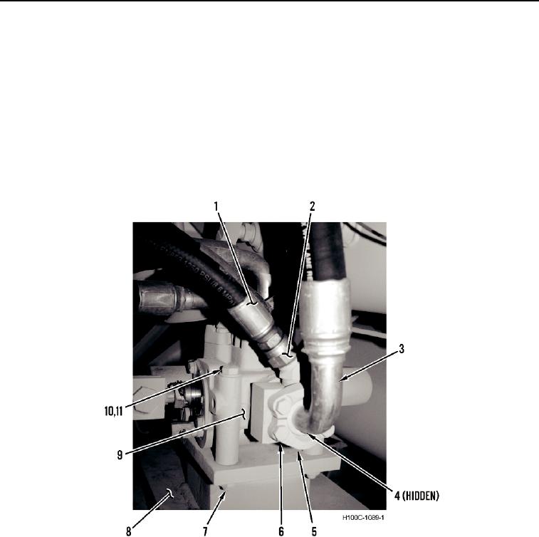
1. Install steering control valve (Figure 3, Item 9), six washers (Figure 3, Item 11), three bolts (Figure 3, Item 10),
and nuts (Figure 3, Item 7) on frame (Figure 3, Item 8).
2. Install new O-ring (Figure 3, Item 4), hydraulic line (Figure 3, Item 3), two split flanges (Figure 3, Item 5) and
four bolts (Figure 3, Item 6) on steering control valve (Figure 3, Item 9).
3. Connect hydraulic line (Figure 3, Item 1) to steering control valve (Figure 3, Item 9) and tighten fitting (Figure 3,
Item 2).
Figure 3. Steering Control Valve, Right Side.
0072
0072-4