
TM 5-3805-255-14
0072
INSTALLATION CONTINUED
00072
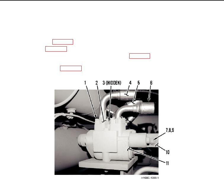
4. Connect steering rod (Figure 4, Item 10), bolt (Figure 4, Item 7), washer (Figure 4, Item 9) and nut (Figure 4,
Item 8) on steering control valve (Figure 3, Item 11).
5. Install three new O-rings (Figure 4, Item 3), three hydraulic lines (Figure 4, Items 4, 5, and 6), six split flanges
(Figure 4, Item 2) and twelve bolts (Figure 4, Item 1), on steering control valve (Figure 4, Item 11).
6. Fill hydraulic reservoir (WP 0018).
7. Remove safety bar (WP 0005).
8. Turn battery disconnect switch to ON position and start engine (WP 0005). Check for leaks and proper steering
operation.
9. Install body access panels (WP 0005).
Figure 4. Steering Control Valve, Left Side.
0072
END OF TASK
0072-5