TM 5-3805-255-14
0072
ADJUSTMENT
00072
WARNING
Before attempting to adjust pressure relief valve, align frame halves and install loader
safety bar in straight ahead position. Failure to follow warning may result in injury or death
to personnel.
1. Remove pipe plug from tee at front end of left-hand steering cylinder and install a test gauge (5,000 psi
capacity).
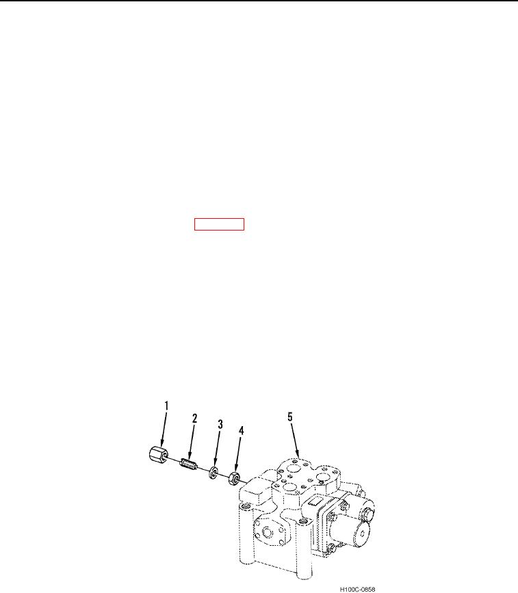
2. Hold capnut (Figure 5, Item 4) and remove nut (Figure 5, Item 1) from steering control valve (Figure 5, Item 5).
3. Hold adjusting screw (Figure 5, Item 2) and loosen capnut (Figure 5, Item 4) on steering control valve (Figure
5, Item 5).
4. Start engine and allow it to run at low speed until hydraulic fluid reaches operating temperature.
5. Turn steering wheel to left until all slack is taken up. Accelerate engine to full throttle and read pressure
indicated on test gauge. Idle the engine. If indicated pressure is not within recommended limits, adjustment is
necessary. Refer to System Pressures (WP 0002) for recommended setting.
6. To adjust pressure, hold capnut (Figure 5, Item 4) and rotate adjusting screw (Figure 5, Item 2) clockwise to
increase and counterclockwise to decrease pressure. Recheck indicated pressure.
NOTE
Must set preload on adjusting screw. Always turn clockwise one half-turn to set spring
preload.
7. When correct pressure is obtained, hold adjusting screw (Figure 5, Item 2) and tighten capnut (Figure 5,
Item 4) on steering control valve (Figure 5, Item 5).
8. Install washer (Figure 5, Item 3), and nut (Figure 5, Item 1) on steering control valve (Figure 5, Item 5).
9. Stop the engine. Remove test gauge and replace pipe plug. Remove safety bar.
Figure 5. Steering Control Valve Adjustment.
0072
END OF TASK
END OF WORK PACKAGE
0072-6

