
TM 5-3805-255-14
0078
INSTALLATION
00078
1. Install main control valve (Figure 4, Item 1), four bolts (Figure 4, Item 6), and nuts (Figure 4, Item 10) on loader.
2. Install two bottom hydraulic line hose flanges (Figure 4, Item 5) on main control valve (Figure 4, Item 1).
3. Install two new O-rings (Figure 4, Item 9), four split flanges (Figure 4, Item 7), and eight machine bolts
(Figure 4, Item 6) on bottom hydraulic lines (Figure 4, Item 8).
4. Install main control valve linkages (Figure 4, Item 4), two clevis pins (Figure 4, Item 3), and two new cotter pins
(Figure 4, Item 2) on main control valve (Figure 4, Item 1).
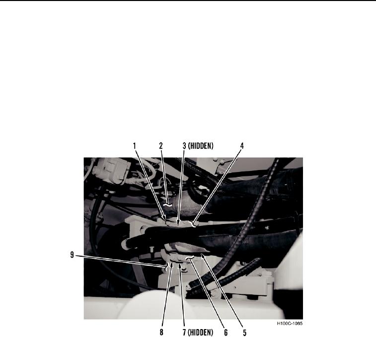
5. Install two side hydraulic line hose flanges (Figure 5, Items 2 and 5) on main control valve (Figure 5, Item 9)
6. Install two new O-rings (Figure 5, Items 3 and 7), four split flanges (Figure 5, Items 4 and 6), and eight machine
bolts (Figure 5, Items 1 and 8), on side hydraulic lines (Figure 5, Items 2 and 5).
Figure 5. Side Hydraulic Lines.
0078
0078-5