
TM 5-3805-255-14
0078
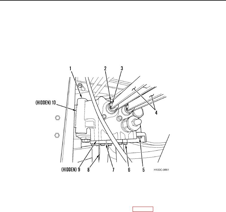
REMOVAL CONTINUED
6. Remove two cotter pins (Figure 4, Item 2), clevis pins (Figure 4, Item 3), and main control valve linkages
(Figure 4, Item 4) from main control valve (Figure 4, Item 1). Discard cotter pins.
7. Remove eight machine bolts (Figure 4, Item 6), four split flanges (Figure 4, Item 7), and two O-rings
(Figure 4, Item 9) from bottom hydraulic lines (Figure 4, Item 8). Discard O-rings.
8. Remove two hose flanges (Figure 4, Item 5) from main control valve (Figure 4, Item 1).
9. Remove four bolts (Figure 4, Item 6), nuts (Figure 4, Item 10), and main control valve (Figure 4, Item 1) from
loader.
Figure 4. Main Control Valve.
0078
END OF TASK
CLEANING AND INSPECTION
00078
Clean and inspect all parts IAW General Maintenance Instructions (WP 0019).
END OF TASK
0078-4