
TM 5-3805-255-14
0078
REMOVAL
00078
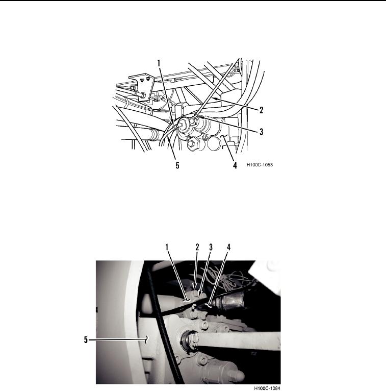
1. Loosen two fittings (Figure 1, Items 1 and 3) and remove two lines (Figure 1, Items 2 and 5) from main control
valve (Figure 1, Item 4).
Figure 1. Gauge Lines.
0078
2. Remove four machine bolts (Figure 2, Item 2), two split flanges (Figure 2, Item 1), and O-ring (Figure 2, Item 3)
from front hydraulic line (Figure 2, Item 4). Discard O-ring.
3. Remove front hydraulic line (Figure 2, Item 4) from main control valve (Figure 2, Item 5).
Figure 2. Front Hydraulic Line.
0078
0078-2