TM 5-3805-255-14
0085
CUTTING EDGE INSTALLATION
00085
General Purpose Cutting Edge Installation
00085
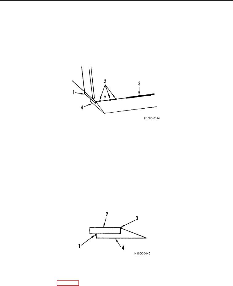
1. Position new cutting edge tip (Figure 6, Item 4) on backing plate (Figure 6, Item 1).
2. Tack weld cutting edge tip (Figure 6, Item 4) to backing plate (Figure 6, Item 1) at front of plate and along back
of tip as shown (Figure 6, Item 2). Start tacks at center of tip as shown (Figure 6, Item 3) and work alternately
between front edge of plate and rear of tip toward both ends.
3. Fix tip ends with firm welds.
Figure 6. Cutting Edge Tip Attachment.
0085
CAUTION
Keep heat penetration (heat build-up) in cutting edge tip and backing plate to a minimum
to control parts warpage.
4. Best results will be obtained by preheating tip (Figure 7, Item 4) and backing plate (Figure 7, Item 2) to 200F
to 300F.
5. Use a 0.312 in. (7.93 mm) fillet weld to join rear of tip (Figure 7, Item 4) to bottom of backing plate (Figure 7,
Item 1). Start a weld 6 in. on either side of tip center and work alternately toward center. Skip 6 in. from
previous welds and work back.
6. Continue to backstep welds alternately on either side of tip center until weld is completed at bucket side plates.
7. Join front tip (Figure 7, Item 3) to front of backing plate (Figure 7, Item 2) in same manner.
Figure 7. Fillet Welds.
0085
8. Remove tack welded brace.
9. Install bucket on loader (WP 0086).
0085-5

