
TM 5-3805-255-14
0093
REMOVAL
00093
NOTE
This procedure explains removal process for one cylinder. Repeat process for other
cylinders.
1. Refer to Piston Inspection (WP 0092) for general information on this procedure.
2. Remove oil pickup tube from engine.
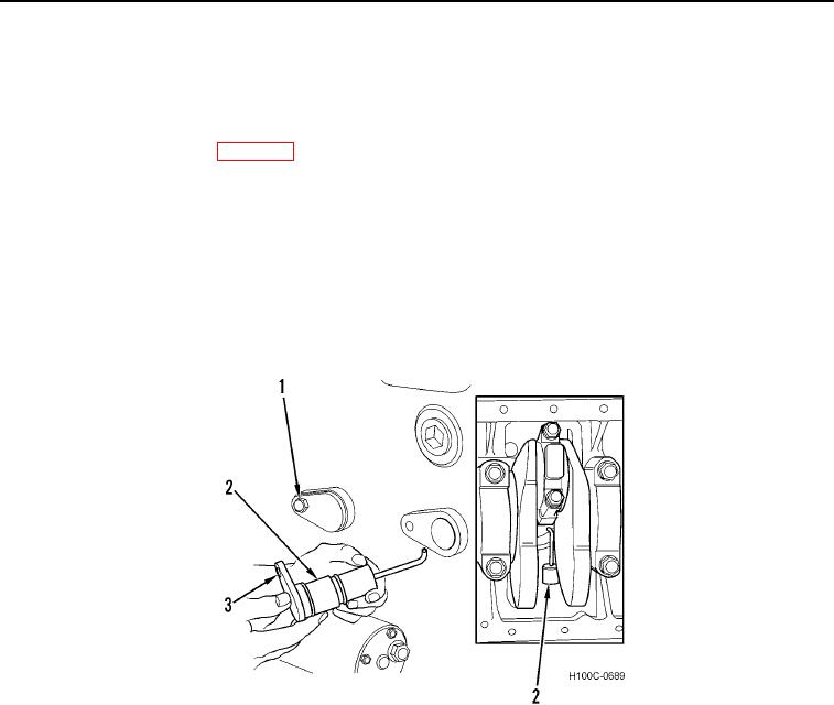
3. Remove piston cooling jet (Figure 1, Item 2) from right side of crankcase as follows:
CAUTION
DO NOT turn jet counterclockwise or jet tube will strike piston skirt. Failure to follow this
caution may result in damage to equipment.
a. Remove capscrew (Figure 1, Item 1) from jet (Figure 1, Item 2).
Figure 1. Removing Piston Cooling Jet.
0093
0093-2