
TM 5-3805-255-14
0092
CLEANING AND INSPECTION CONTINUED
5. Thick wall cooling jets (3/8 in. OD tube) are accurately aligned when manufactured to provide correct spray
angle. Stiffer construction ensures that they will retain this angle through normal handling. If a jet tube is
obviously abused and damaged, it must be replaced.
END OF TASK
ASSEMBLY
00092
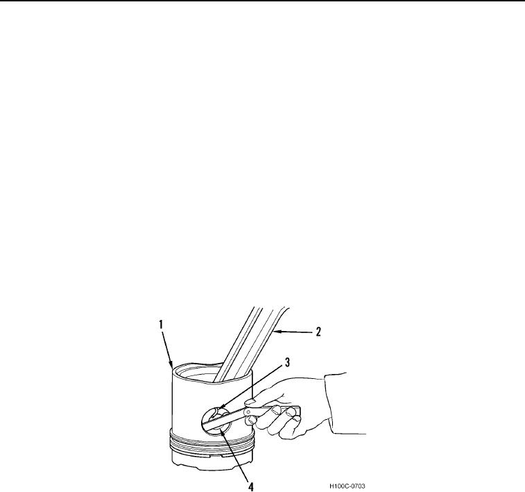
1. Generously coat piston pin (Figure 8, Item 3) with Molykote dry lubricant.
2. Position connecting rod (Figure 8, Item 2) inside piston (Figure 8, Item 1). Align bushing in rod with piston pin
holes in piston and push piston pin (Figure 8, Item 4) completely into position.
3. Squeeze pronged ends of piston pin retainer rings (Figure 8, Item 3), and install one ring in groove on each
side of piston (Figure 8, Item 1) to secure piston pin (Figure 8, Item 4).
4. Check fit of piston pin in piston for proper end clearance as follows:
a. Push one end of piston pin (Figure 8, Item 4) until it reaches a definite stop against retainer ring (Figure 8,
Item 3) on opposite side of piston (Figure 8, Item 1).
b. Position a feeler gauge between end of pin (Figure 12, Item 4) that was pushed in and retainer ring (Figure
8, Item 3) to check for end clearance. Clearance must be 0.002 to 0.030 in. (0.051 to 0.076 mm).
Figure 8. Checking Piston Pin End Clearance.
0092
0092-9